Assignment: Create a new sense using wearables

There is a piece of folk wisdom here in the US that says one can feel it in their bones when the weather is changing. While this lends itself to more than a few caricatures of old codgers sitting on the porch, there is some anecdotal evidence that arthritic joints could be susceptible to the rapid shifts in atmospheric pressure that occurs right before a weather event.
For my assignment, I decided to build a wearable that would codify this otherwise mystical meteorology: a knee brace that uses a barometric pressure sensor to activate a mini vibration motor when the pressure falls below a certain threshold, indicating bad weather.

Background

Barometers are used to predict the weather by measuring the changes in atmospheric (or barometric) pressure. When the barometric pressure decreases rapidly, that is a good indicator that rainy or stormy weather is on the way. For more info why, see here.
I chose to locate my wearable on the knee because of the pervasiveness of the trope of the old man and his bad knee. As is the case with most tropes, I couldn’t rightly say where it originated. Regardless, the image of an old farmer, sitting on a porch while mumbling some folksy nonsense, is burned into mine––and I would wager many Americans’––imaginations. This is a manifestation of that image.
Materials Used (plus tips!)
- Lilypad Arduino ATmega32u4 v. 10
- I do not recommend using this board. It is extremely fragile: the micro USB port snapped off immediately. I’m going to try Adafruit’s Flora next time around.
- Lilypad Coin Cell Battery Holder with Switch
- BMP180 Barometric Pressure Sensor Breakout Board (4 pins)
- You will need to solder the header pins on.
- Mini Vibration Motor Disk
- Smaller than a dime but packs a big enough punch.
- 1N4002 Diode
- Prevents surges from the motor getting to the microcontroller.
- 1 µF Capacitor
- Prevents surges from residual spinning of motor parts.
- 2N3904 Transistor
- Acts a switch that turns on the motor when power passes through it.
- 220 Ohm Resistor (red, red, brown, gold)
- The motor packs a considerable punch at when receiving the full 3.3V from the microprocessor and burns up faster. Put in a resistor to ease up the vibration and help it last longer.
- Alligator Clips for Prototyping
- Make connections with alligator clips before spending time sewing. Learned this the hard way.
- 2-ply Conductive Thread
- Sewing needle
- Scissors
Disclaimer: The links above are not endorsed by me or anyone else and are for informational purposes only.
Prototyping
In order to wrap my head around how to organize the circuit on the fabric before starting construction, I made the following circuit prototype using conductive tape in my notebook:
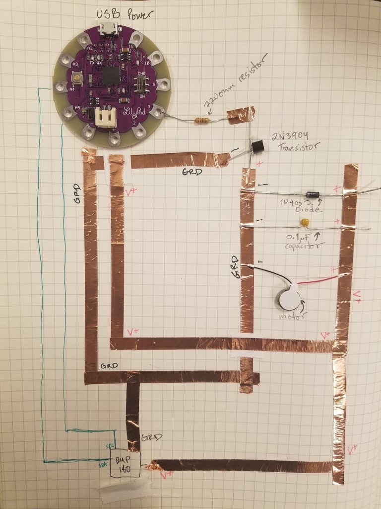
So I initially hooked this up to power via the USB cord to my computer. The only code I was running at that time was the example code given along with the SFE_BMP180 library for the barometric pressure sensor. I wanted to test both the sensor and the actuator sides of the circuit. When powered and running the example code, the following SHOULD happen:
- when I open Serial in the Arduino IDE, I should see a running print out of the current barometric pressure reading
- the motor should vibrate continuously
This is what ACTUALLY happened:
- while the code uploaded without errors, nothing showed up on Serial, not even the programmed error messages
- the motor buzzed at a variable rate and would occasionally start and stop
RUDE.
So WTF was going on? (Spoiler Alert: I don’t know.)
Code
Troubleshooting
In order to try and figure out what was up with the BMP180 sensor, I did the following:
- looked up the datasheet…
- …apparently this version of the sensor breakout board I bought from Tinkersphere doesn’t exist? The closest I could find was this for the GY-68.
- made sure I was connected to the right pins on the Lilypad for SCL and SDA
- they are labeled but this Arduino forum post seems to indicate that are the same as on an Uno
- tried using one of the cree Circuit Board Express microcontrollers available in the soft lab.
- using this I was able to get the sensor to show up in serial at least but not show any readings
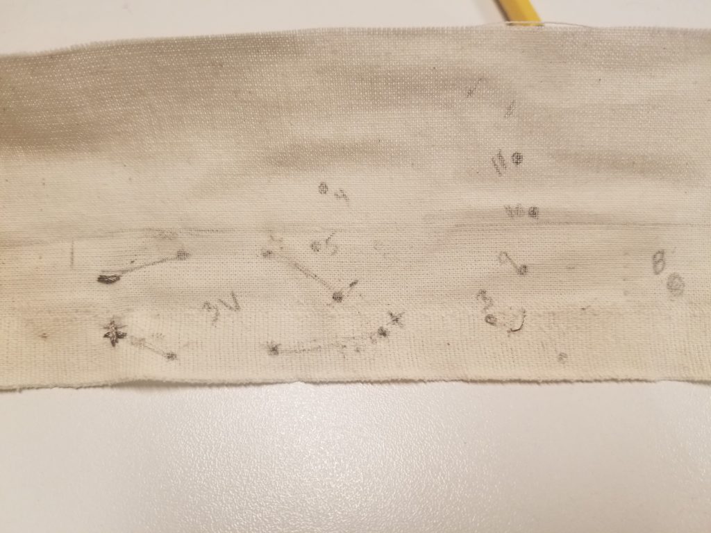
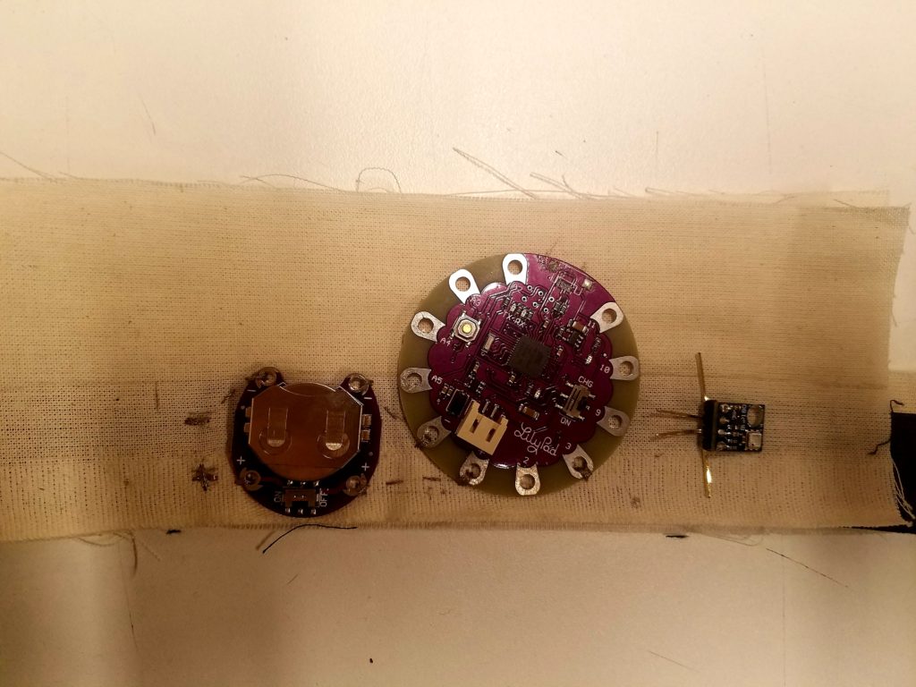
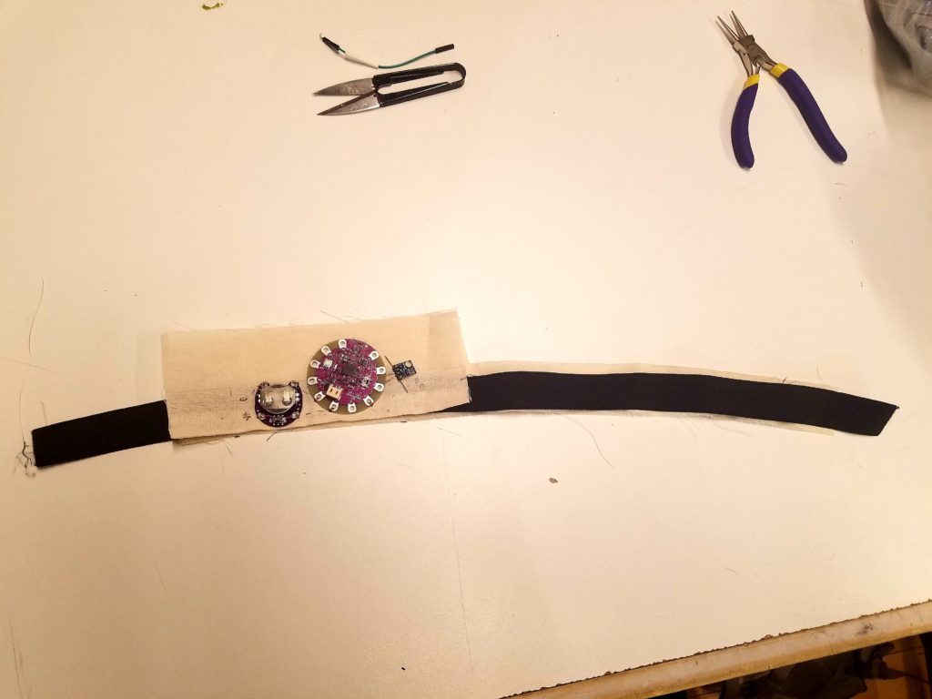
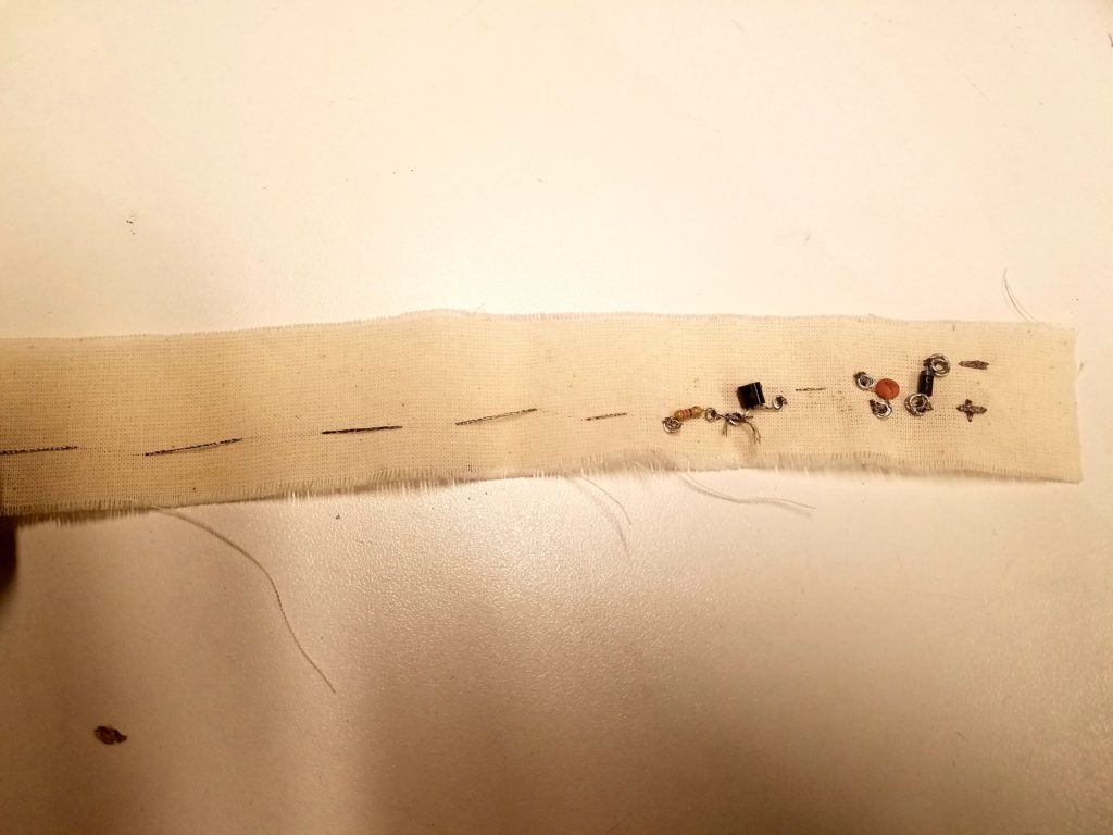
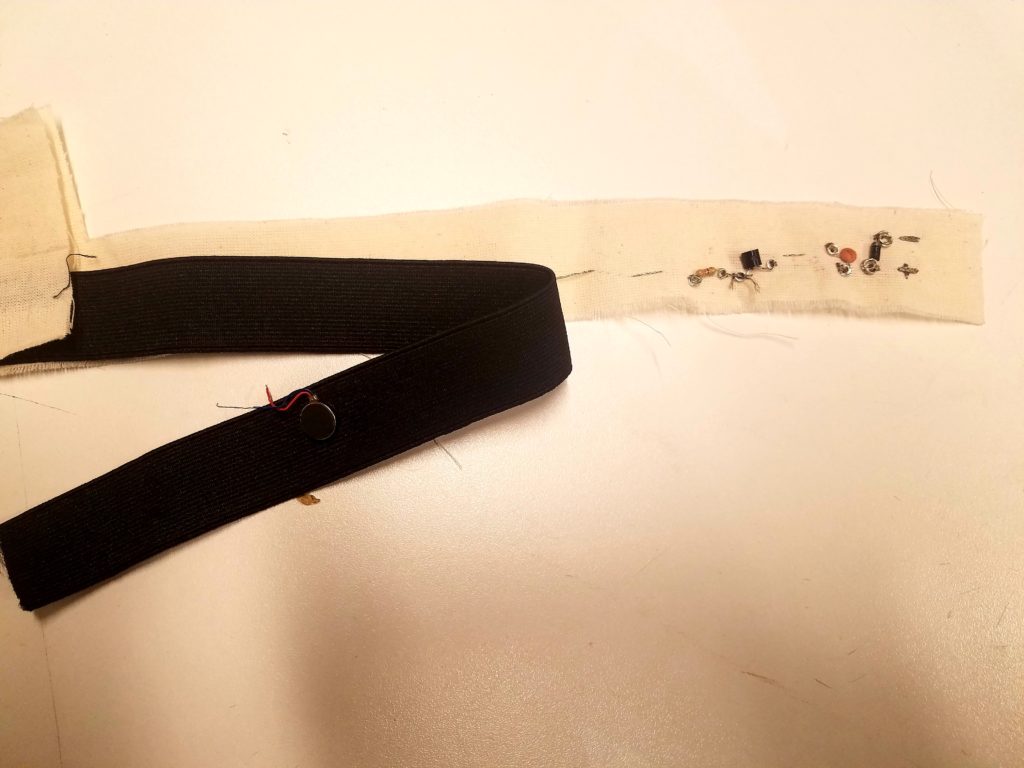
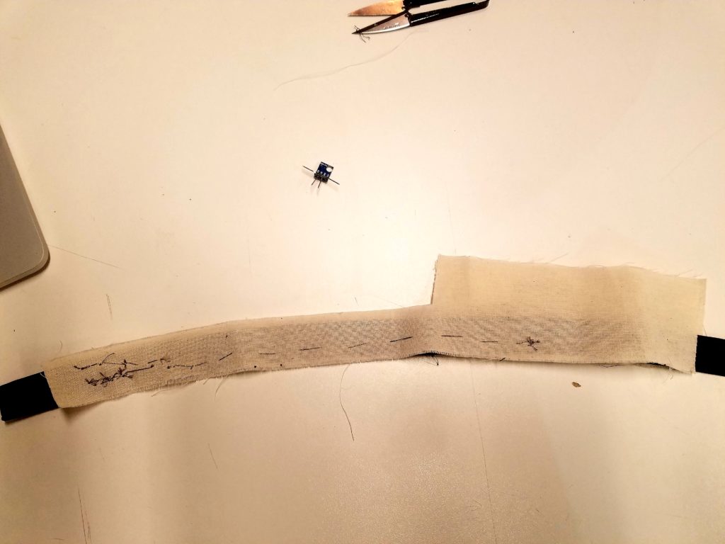
Construction
Leave a Reply
You must be logged in to post a comment.