Folk Wisdom Wearables, Part 2: A Watched Pot Never Boils

The saying “A watched pot never boils” is used to describe the phenomenon of time seemingly slowing to a halt whenever your mind is consumed with waiting for something.
I took this idea to its literal and logical conclusion and created a wearable that will turn off a stovetop whenever the wearer looks at it.
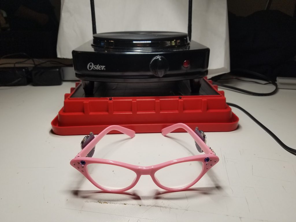
The wearable consists of two parts:
- a portable hot plate
- cat-eye eyeglasses
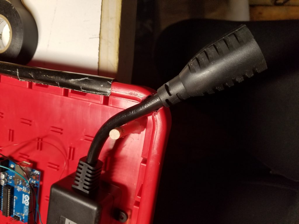
The hot plate is mounted on a platform that contains two IR PHOTOTRANSISTORS connected via an ARDUINO UNO to a POWERSWITCH TAIL––a relay that controls the flow of electricity between the appliance and wall power.
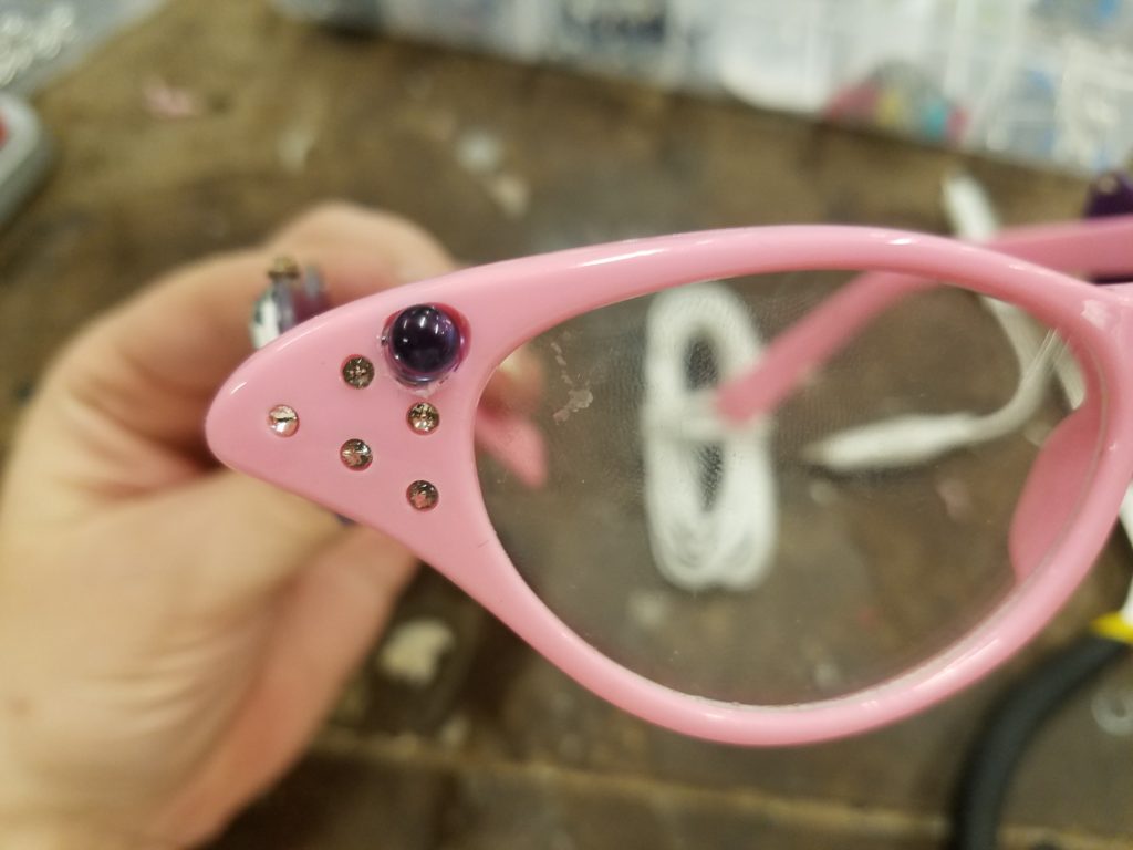
Making the Glasses
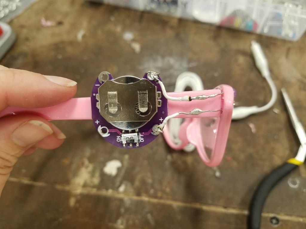
Mimicking the rhinestone bedazzlement, the cat-eye eyeglasses have been fitted with two IR LEDS powered by two 3V coin cell batteries. I used the sewable Lilypad coin cell holders because they have an on/off switch. Without the ability to easily disconnect the battery power, the batteries would drain in a matter of hours. They also had the added bonus of the purple color coordination with the LEDs.
I tested the LEDs by using my camera phone since the IR light is not visible to the naked eye:
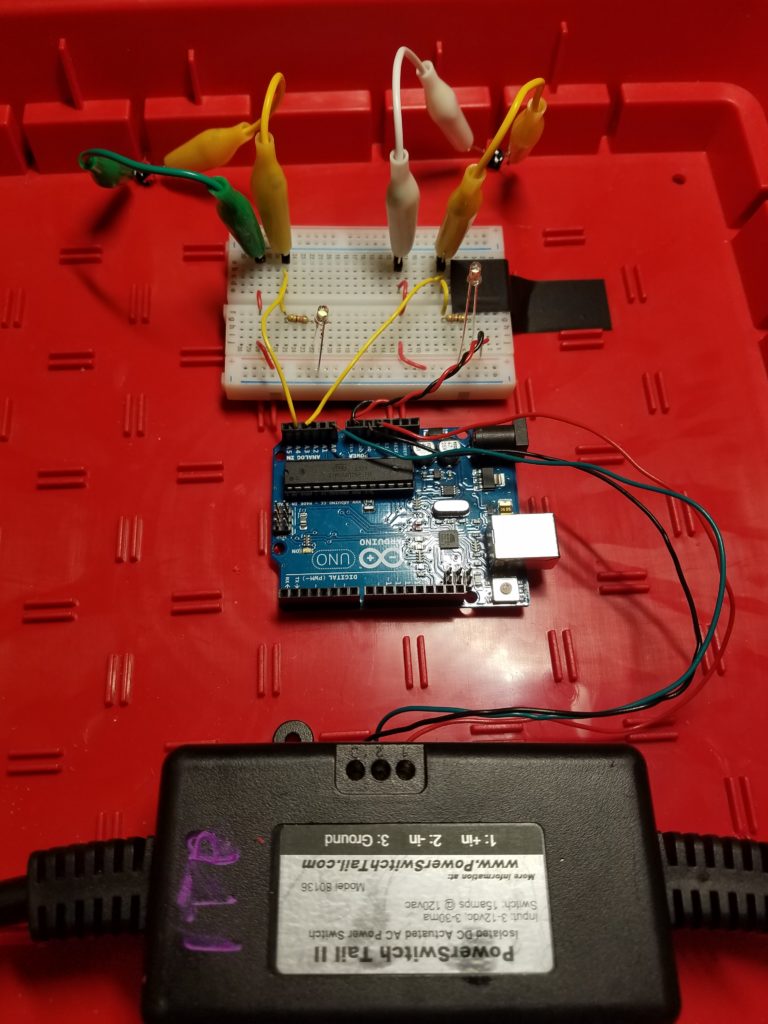
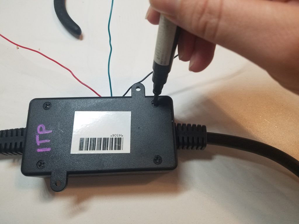
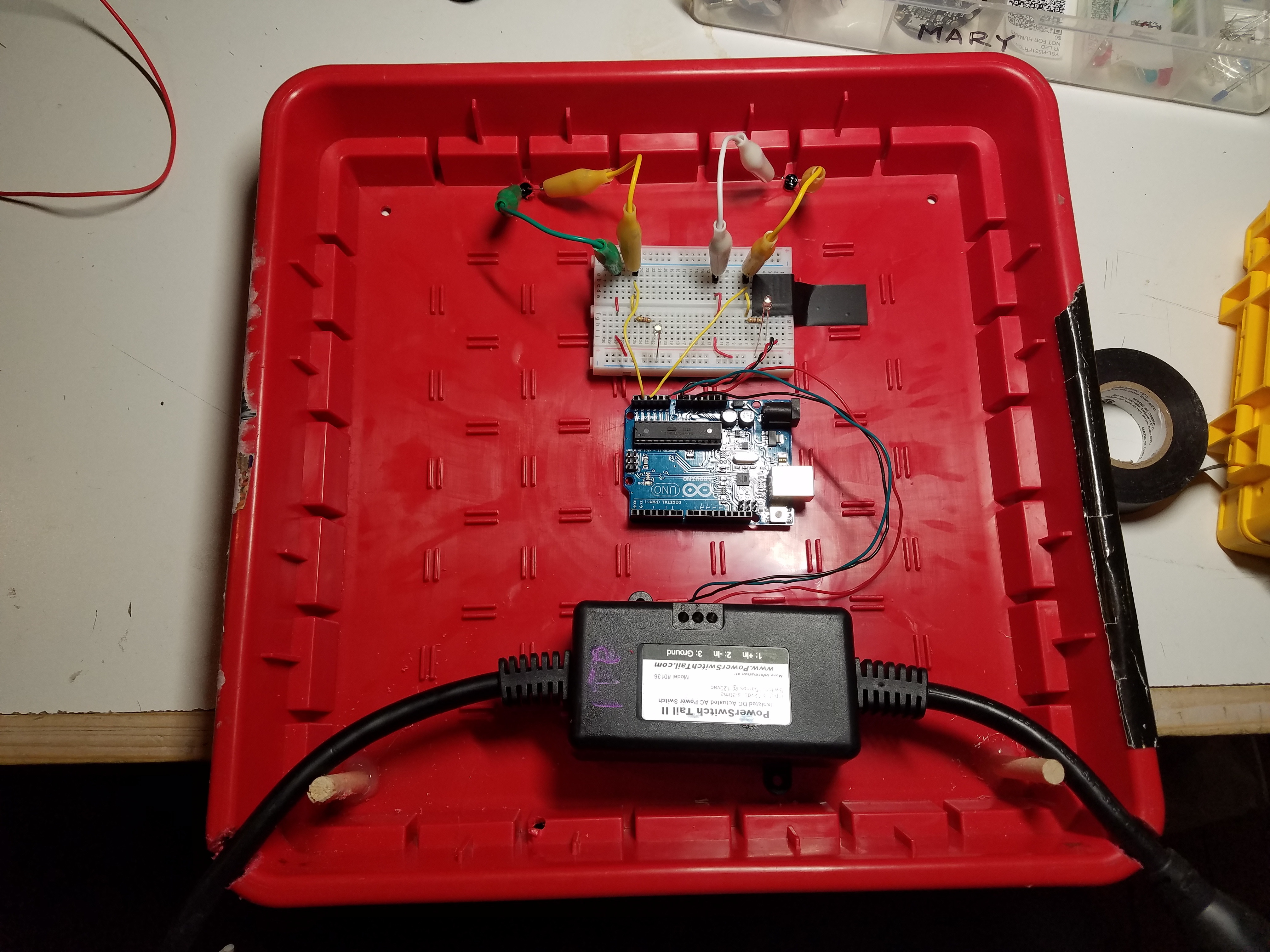
Setting Up the Powerswitch Tail and Phototransistor
The Powerswitch Tail is essentially a relay in a case that is set up for controlling wall power supplied to appliances via a microcontroller. They are used in hobbyist electronics to build apps and other remote switches for turning power on and off to household electronics. I was relieved to learn of its existence because that did not mean I had to build one of my own.
The PST is set to Normally Open by default so I had to open it up and resolder JP1 to NC (Normally Closed). I knew how to do this thanks to the datasheet. This would set it so that power would flow continuously between the wall socket and the appliance until the relay was activated, thus shutting off the power.
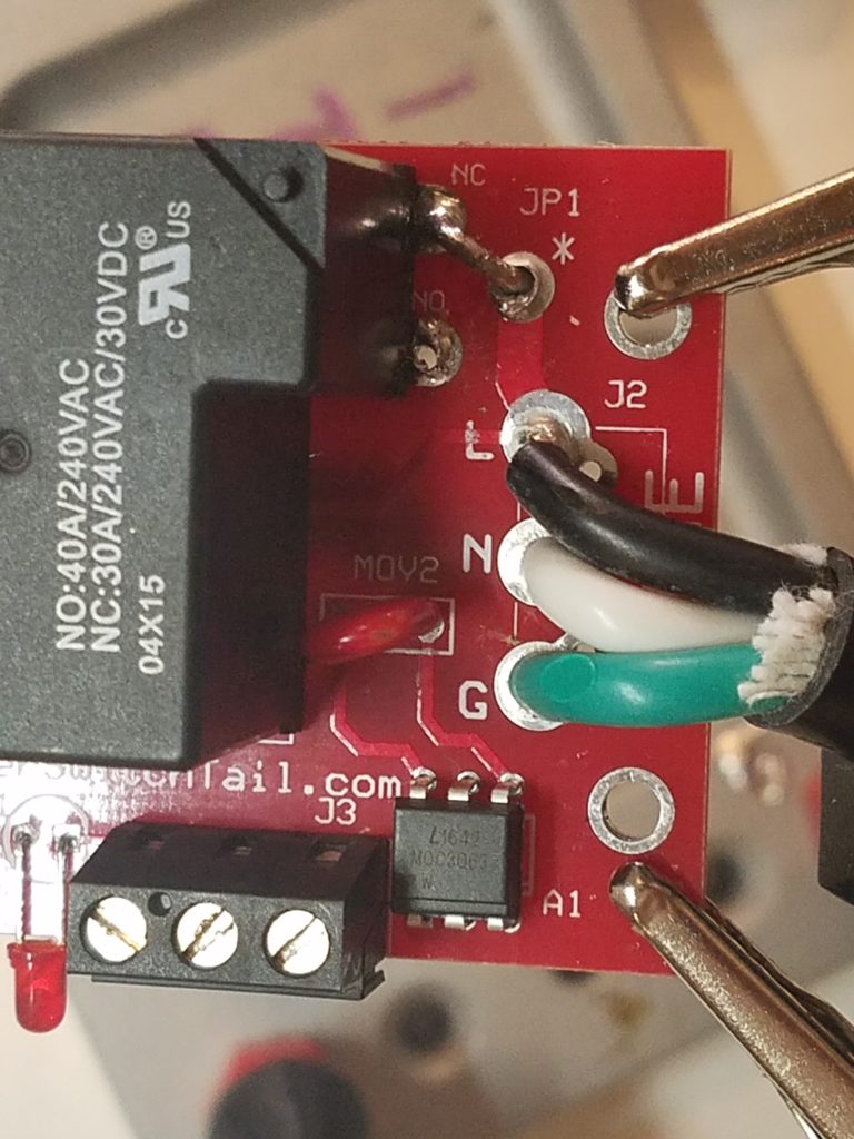
Then I made sure to screw in wires for each terminal labeled as such:
- 1: + in (POWER)
- 2: – in (DATA)
- 3: Ground (GROUND)
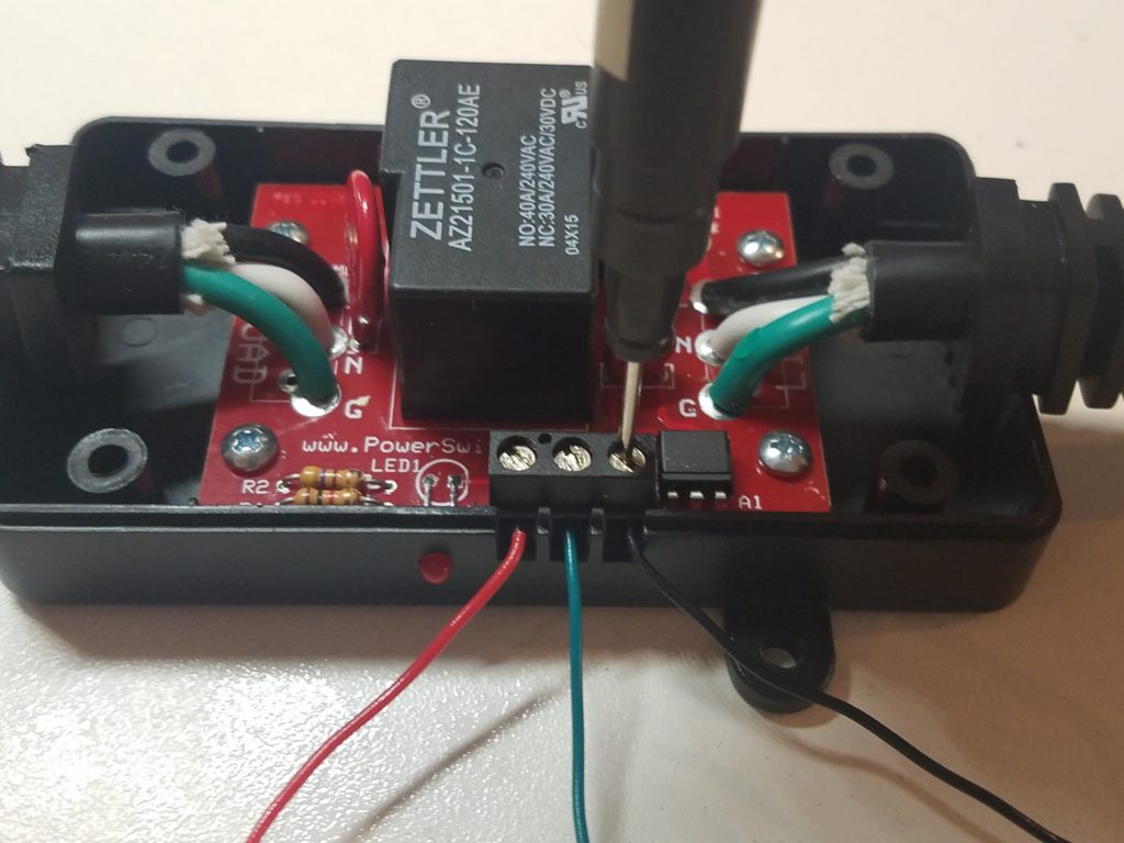
And I connected them to 5V, A0, and GRD respectively.

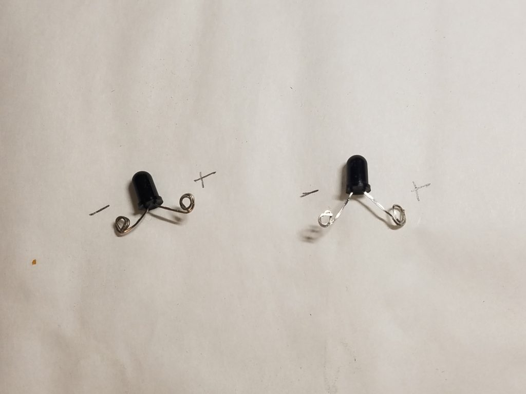
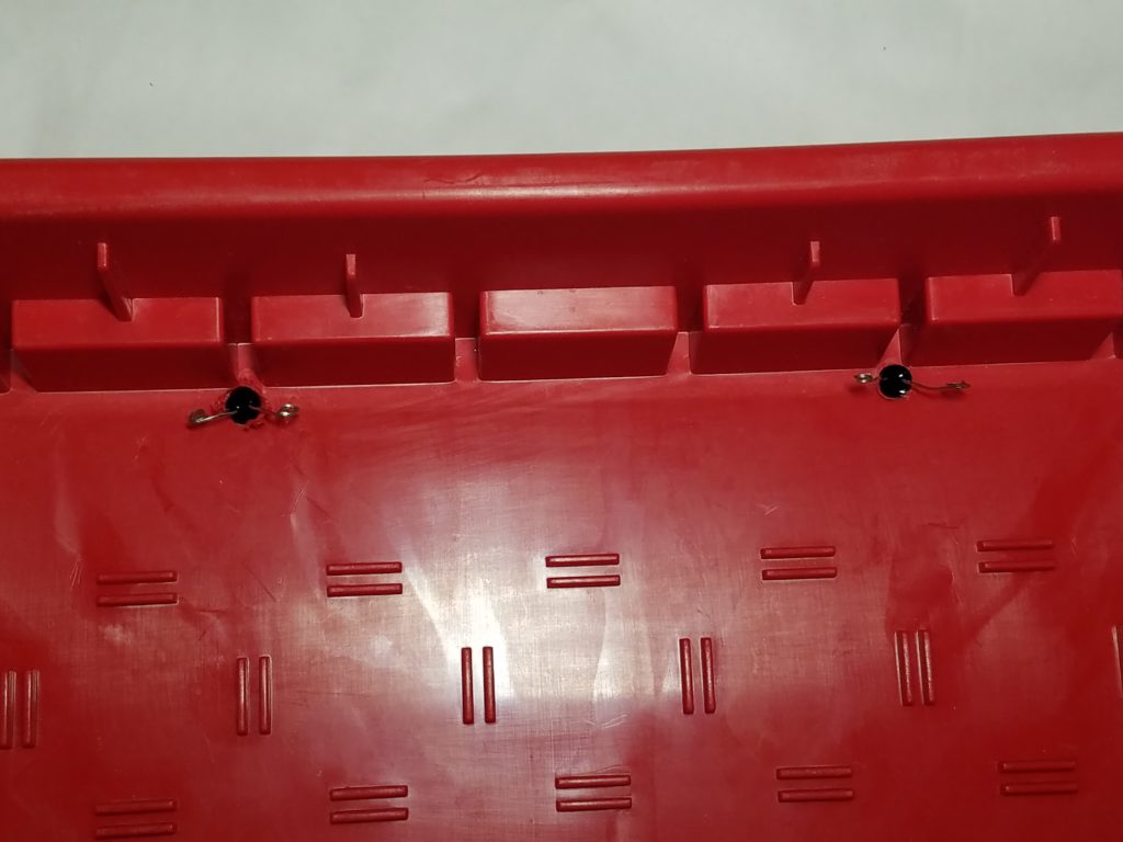
The IR PHOTOTRANSISTORS circuit as follows:
- CATHODE connects to Vin
- ANODE connects to Analog PINs A1-A4
- a CLEAR LED connects to a 200 ohm RESISTOR and the IT PHOTOTRANSISTOR ANODE
Testing The System
It Works!
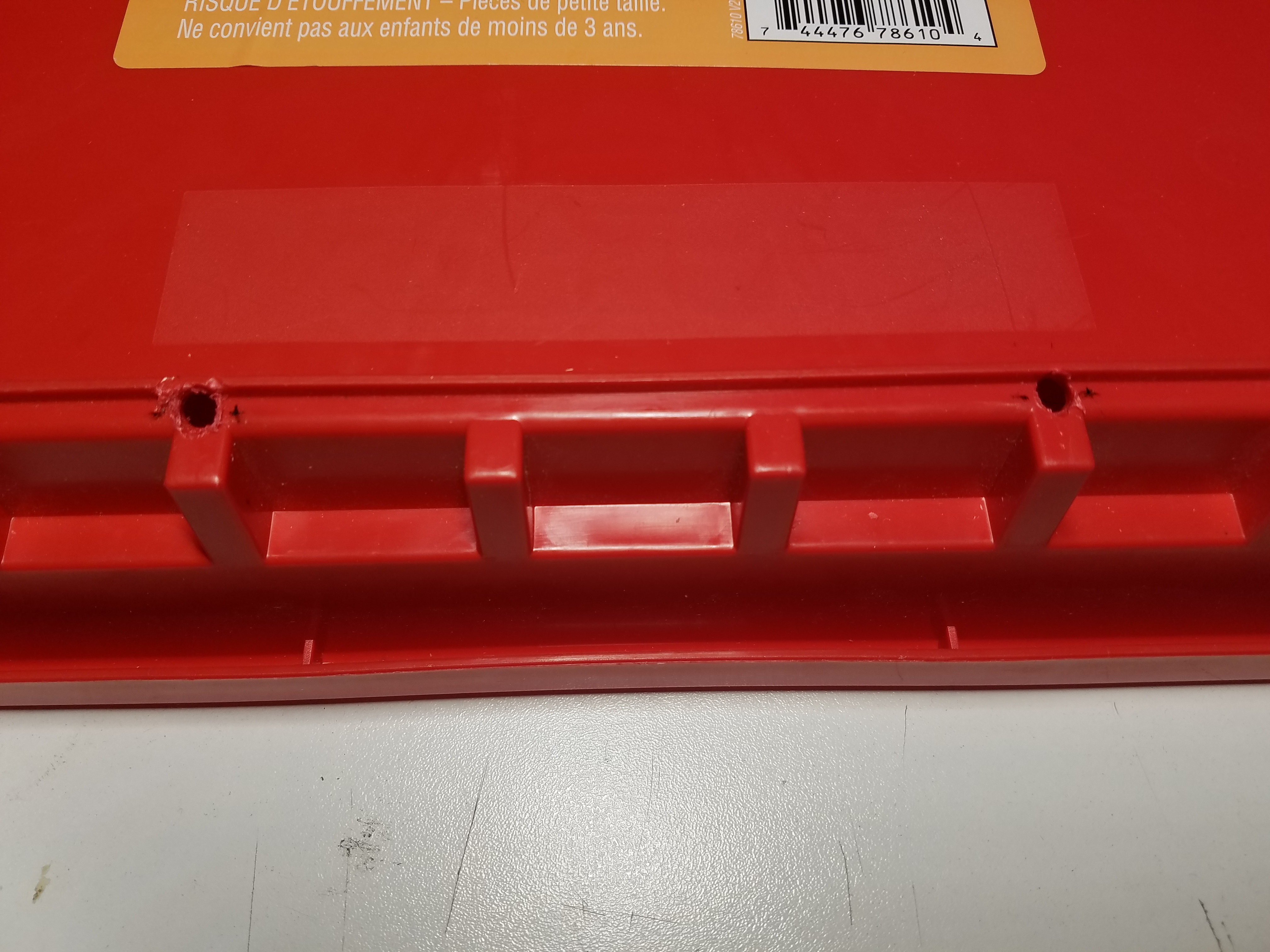
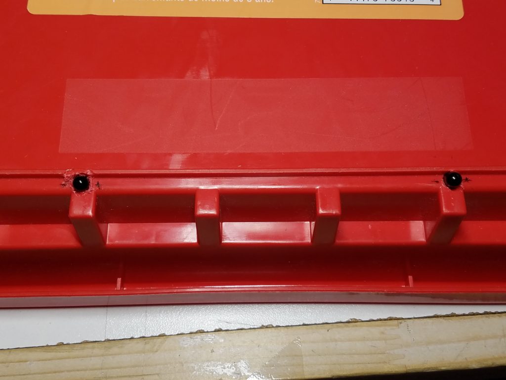
Mounting the Hot Plate and IR Phototransistors
Leave a Reply
You must be logged in to post a comment.